Bish's BH Project

For everything Coin-Op and Arcade related

Moderators: machine.slave, Doc Kaos, mark, jasonec, CongoBongo, monkeybug

User avatar
Bish500
Canadian Club
Canadian Club
Posts: 1791
Joined: Sat Aug 27, 2005 9:56 pm
Location: Peterborough, Ontario, Canada

Bish's BH Project

Postby Bish500 » Sun Aug 23, 2009 9:18 pm

As some of you know, I ended up with quite a Black Hole project last fall. For a long time, I just had the head unit, and then I managed to get the body this spring. The whole unit had been in storage, by what we've been able to figure out, for 20 years.

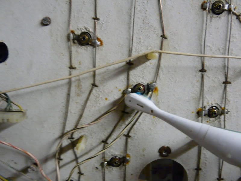
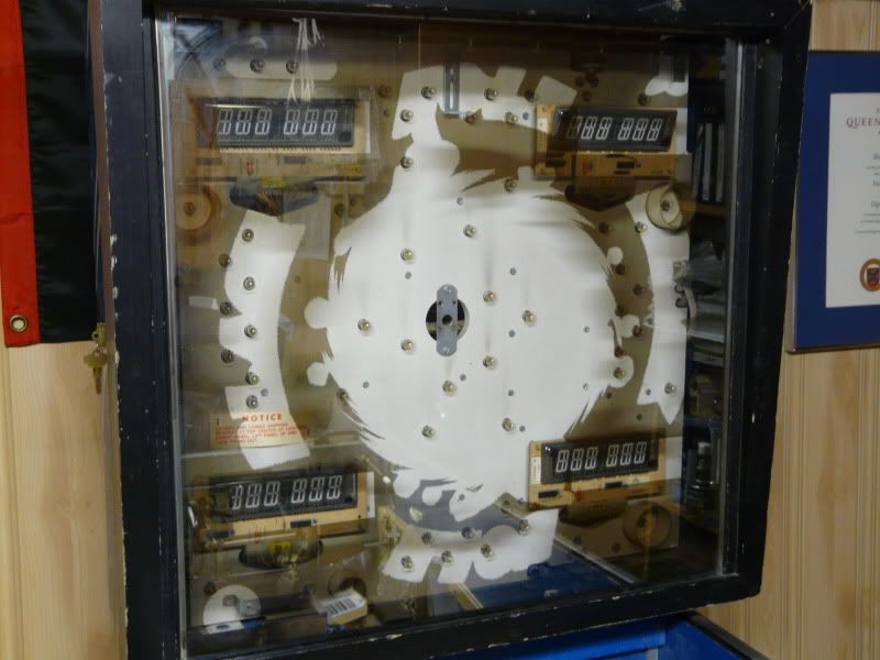
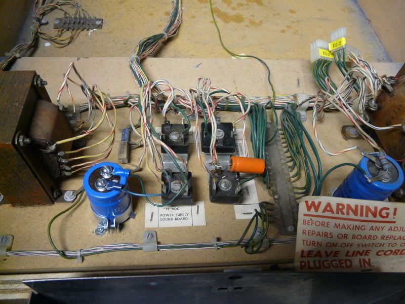
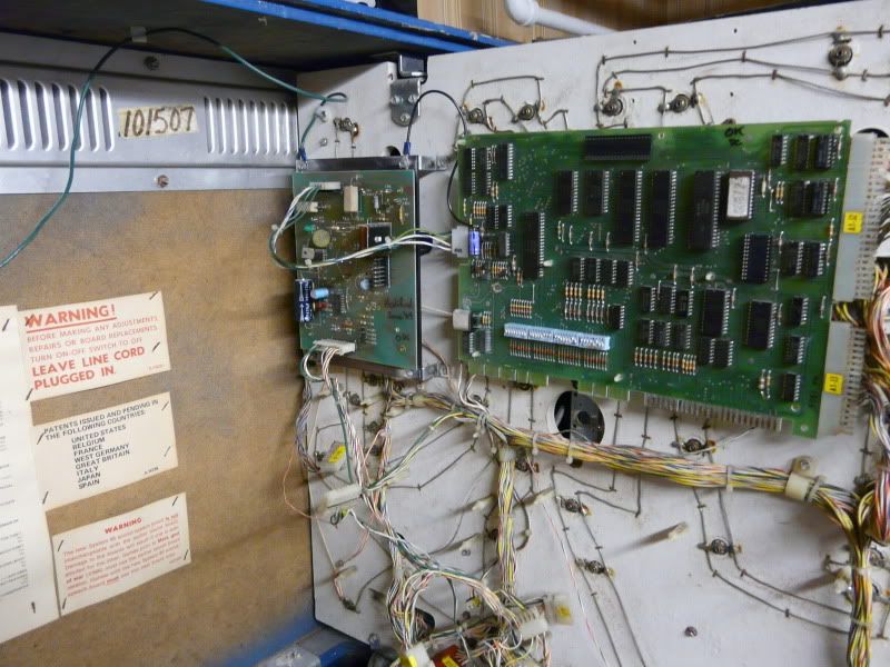
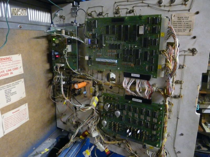
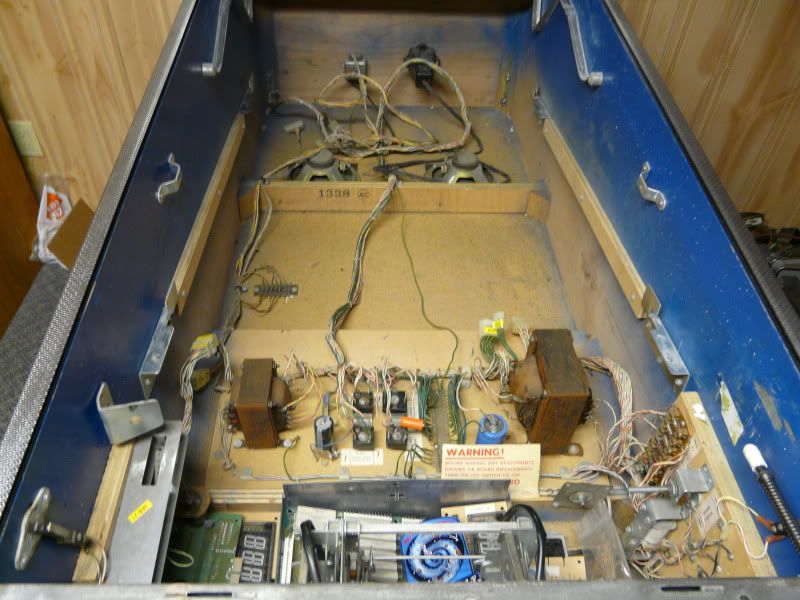
The game was missing all of the upper displays, the motor to spin the vortex on the backglass is seized. There was some acid damage on the CPU board (although it doesn't seem to have damaged any of the components). One of the pop bumper driver boards was missing. There is at least one burnt coil. There was the requisite mouse poop in the lower cabinet.

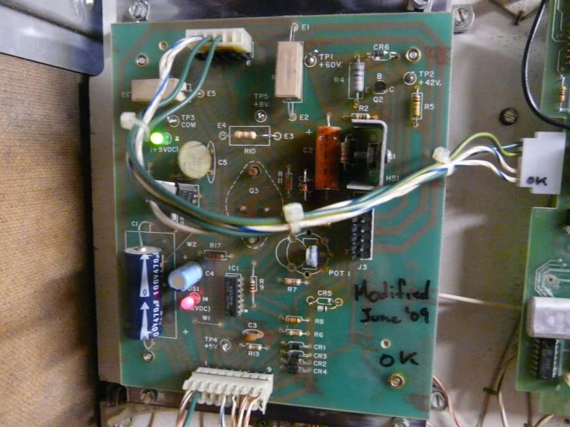
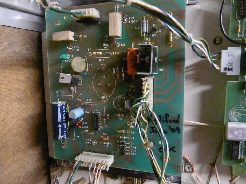
I've had some time to work on it over the past few weeks. A friend offered to do the electronic repairs and upgrades on the boards.

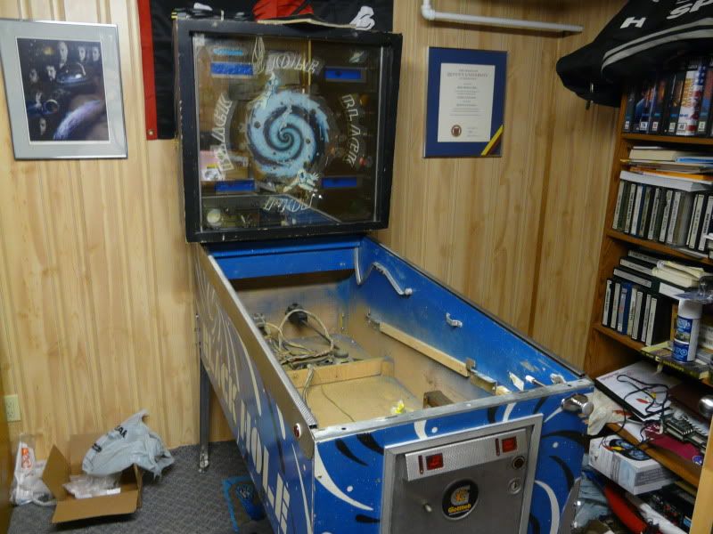
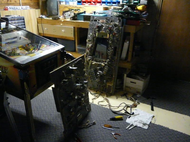
Body & Head, Reunited

Image

Image

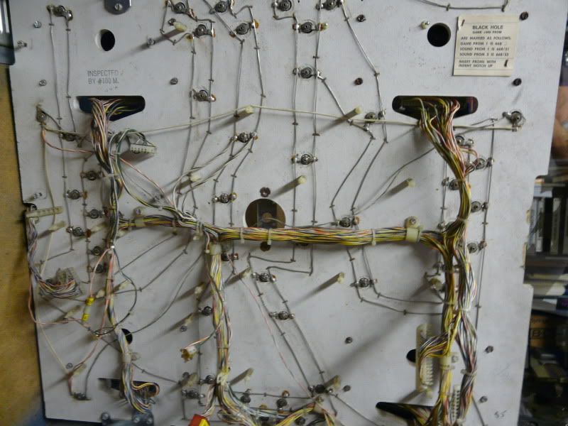
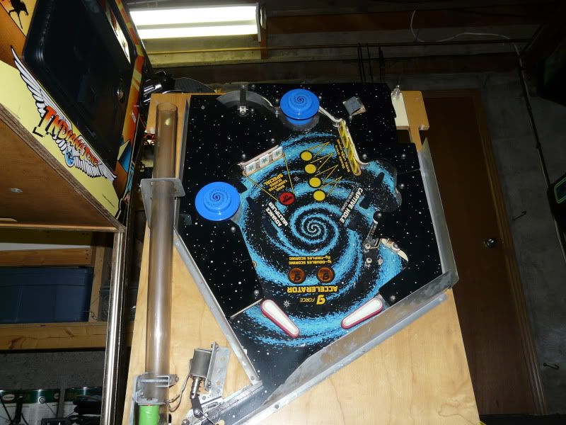
Playfields being worked on

Image

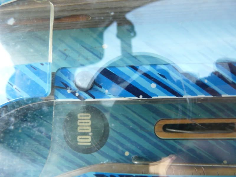
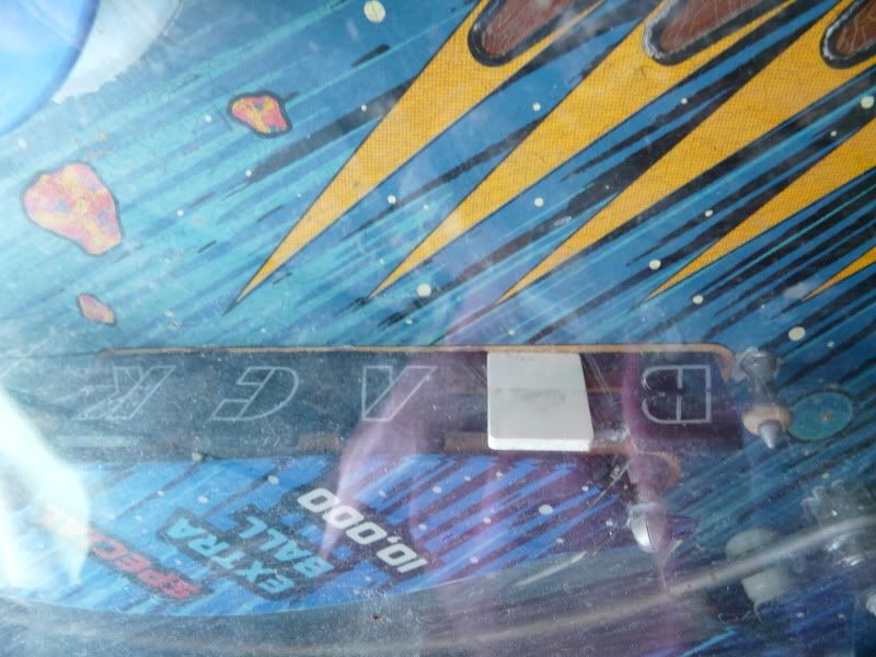
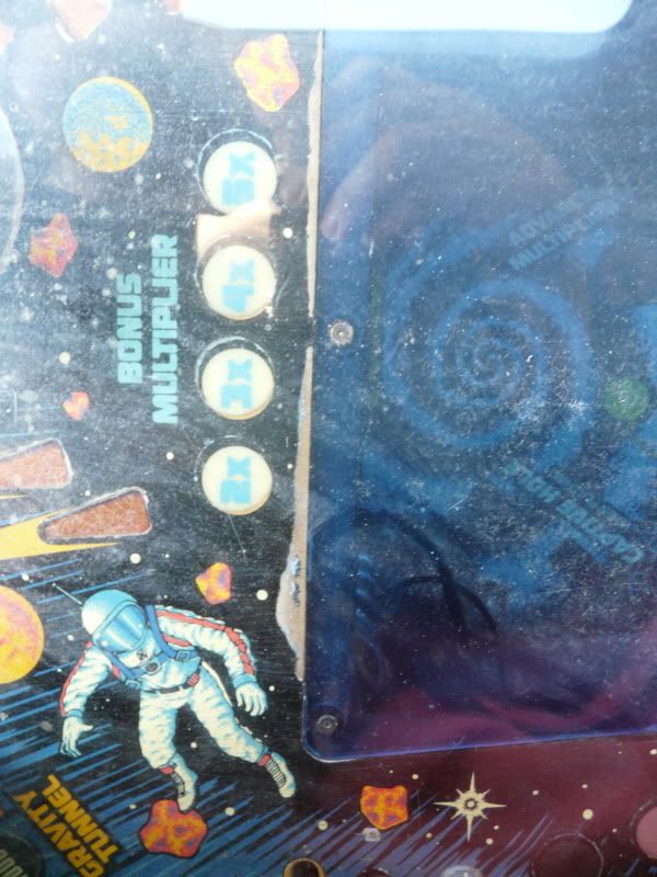
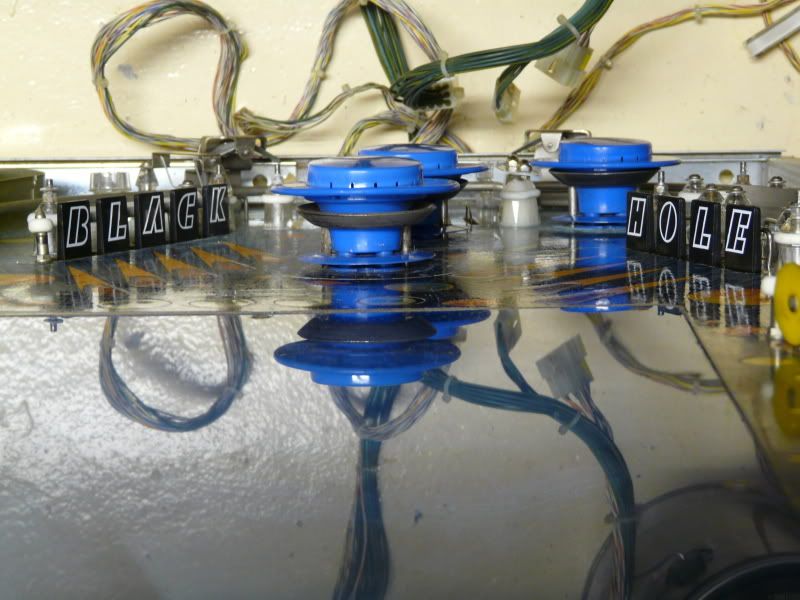
Main Playfield - The drop targets spell "Black Hole" again.

Image

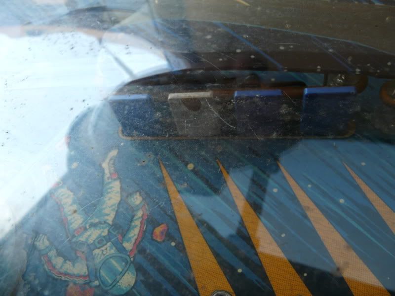
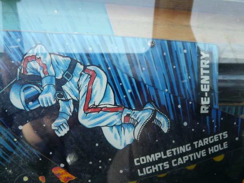
Lower Playfield - New Drop Targets

Image

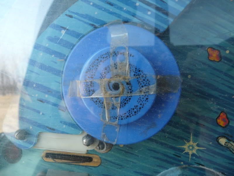
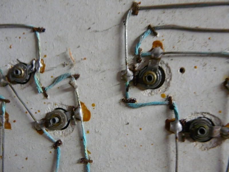
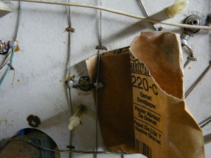
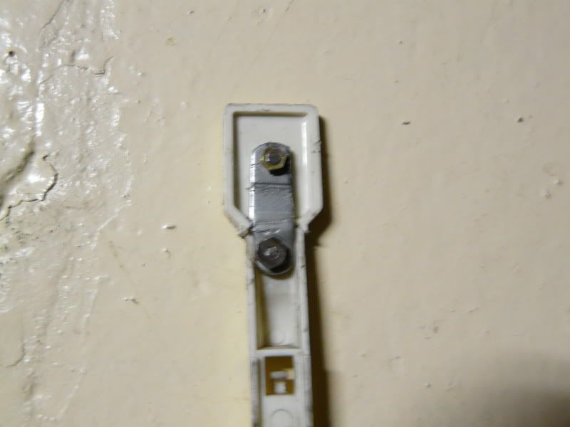
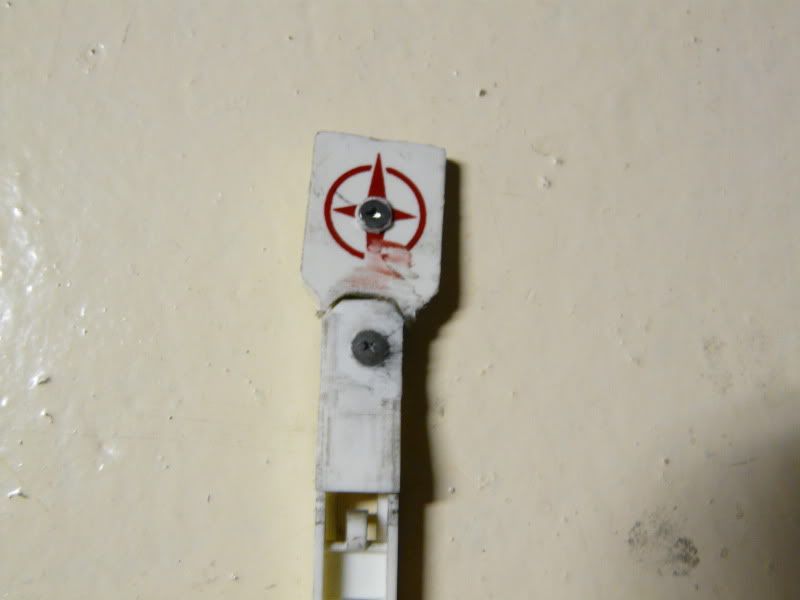
Here are the drop targets I removed. Most were not the correct target. One was broken off completely. One was the worst/most ingenious repair I've seen in a long time.

Image

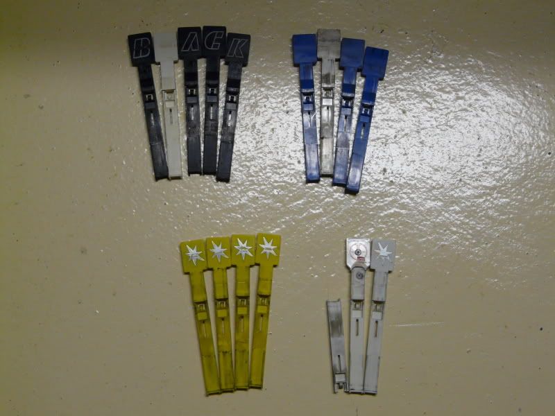
Worst/Most Ingenious Repair

Wouldn't it be cheaper/less time intensive just to buy and install a new one?

Image

Image

I'm in the midst of stripping the main playfield down, cleaning, and replacing bent metal posts, yellowed star posts, rubbers, bulbs, and a new set of repro plastics. It's really dirty after 20 years of just sitting around.
Image

User avatar
ancientgames
Canadian Club
Canadian Club
Posts: 1743
Joined: Mon Oct 23, 2006 10:23 pm
Location: Lindsay/Peterborough

Postby ancientgames » Sun Aug 23, 2009 9:34 pm

Aaaaah but she'll be nice when done. You only have a few weeks left before school is back in so get'r'done!

:D

User avatar
Bish500
Canadian Club
Canadian Club
Posts: 1791
Joined: Sat Aug 27, 2005 9:56 pm
Location: Peterborough, Ontario, Canada

Postby Bish500 » Sun Aug 23, 2009 9:38 pm

ancientgames wrote:Aaaaah but she'll be nice when done. You only have a few weeks left before school is back in so get'r'done!


Looks like a fair bit of work ahead of me still. I'm hoping to have it playable by Christmas time.

BTW...We don't mention the "S" word in August. :-(
Image

User avatar
RayB
Crazy Canuck
Crazy Canuck
Posts: 6615
Joined: Wed Jun 23, 2004 12:22 pm
Location: Toronto, ON
Contact:

Postby RayB » Sun Aug 23, 2009 9:42 pm

Good luck! It's a cool looking and sounding pin.
.
Image

User avatar
Bish500
Canadian Club
Canadian Club
Posts: 1791
Joined: Sat Aug 27, 2005 9:56 pm
Location: Peterborough, Ontario, Canada

Postby Bish500 » Sun Aug 23, 2009 9:56 pm

Here are some pictures of what it looked like when I first got it (through dirty top glass):

Image

Image

Image

Image

Image

Image
Image

User avatar
axe
Canadian Club
Canadian Club
Posts: 1241
Joined: Sun Aug 24, 2008 6:42 am
Location: GTA EAST SIDE!

Postby axe » Sun Aug 23, 2009 10:58 pm

Heheh, it was a "B ACK HO E" machine! (not not really)

SHould be sweet when done, Heres hoping you get your "Hole" all cleaned up and working!

:D

User avatar
Bish500
Canadian Club
Canadian Club
Posts: 1791
Joined: Sat Aug 27, 2005 9:56 pm
Location: Peterborough, Ontario, Canada

Postby Bish500 » Tue Sep 01, 2009 11:04 am

I'm working mostly on the head right now. The Backboard GI wires were corroded. When I got the machine, there were 3 "AA" batteries soldered to the CPU and bundled up with black electrical tape. There was no blocking diode, and the theory is the batteries leaked when the game tried to charge the batteries (plus I figure they were attached for 20 years, leaking acid). It could have been much worse, as the original "Data Sentry" NiCad battery would have likely done more damage. Amazingly, the reset and clock sections of the CPU still work.

Back to the GI wires....

Image

I sanded all the wires with 220 grit sandpaper. I tried to get under the wires (between the wire and the board) whenever possible. To make things worse, the head was obviously "damp" at some point, as there was a lot of rust on the screws, staples, and t-nuts. I tried to get the worst off with the sandpaper.

Image

All the wires are shiny now.

Image

I used a mixture of 100ml white vinegar and 100ml water (50/50 mixture) to wash the wires and the lamp sockets with. The acid in the vinegar neutralizes the alkaline from the batteries. This should help to keep the corrosion from coming back. I used a "spinbrush" (battery powered toothbrush) to really get the mixture to in the nooks and crannies. Afterward, I used 99% pure isopropyl alcohol on the spinbrush to displace the water that may have gotten into the sockets.

Image

Now, once I'm sure everything is dry, it's time to test continuity on all the wires and lamp sockets. If everything tests OK, I'll remount all the circuit boards.

This is how the head is looking now:

Image

When I got the machine, it had no displays in the head. I picked up some cheap, and have mounted them. I've removed the spinning disk, granger motor (which is dead), and also the inner backglass. I've relamped the head (I was amazed to find the head takes 80+ bulbs...#44s and #455s (which are the blinking lights under the spinning vortex disk).

In the body, I've replaced the "orange" filter cap with a new 24V, 12000mF capacitor.

Image

That's all, so far.
Last edited by Bish500 on Thu Sep 03, 2009 11:07 pm, edited 1 time in total.
Image

User avatar
The_*Real*_Menace
timbit
timbit
Posts: 122
Joined: Sun Dec 04, 2005 2:31 pm
Location: Ontario

Postby The_*Real*_Menace » Wed Sep 02, 2009 12:25 pm

Not sure what that other orange cap is doing in the cab soldered to the bridge / ground buss, but I'd get rid of that.

Very nice job on the ground braid!

What's next? Connector pins? ;)

D

User avatar
Bish500
Canadian Club
Canadian Club
Posts: 1791
Joined: Sat Aug 27, 2005 9:56 pm
Location: Peterborough, Ontario, Canada

Postby Bish500 » Thu Sep 03, 2009 11:26 pm

The_*Real*_Menace wrote:Not sure what that other orange cap is doing in the cab soldered to the bridge / ground buss, but I'd get rid of that.

Very nice job on the ground braid!

What's next? Connector pins? ;)

D


Thank you. It's always good to have an expert to rely on.

Image

BTW...[you'll love this]...the orange cap isn't soldered there...the leads are just wrapped around the BR lugs/wires.

I started working on the connector pins tonight. Several hours later, I had only made minimal progress. Repinning is a lot of work. You weren't kidding!
Image

User avatar
The_*Real*_Menace
timbit
timbit
Posts: 122
Joined: Sun Dec 04, 2005 2:31 pm
Location: Ontario

Postby The_*Real*_Menace » Fri Sep 04, 2009 8:11 am

Thank you. It's always good to have an expert to rely on.


No problem. Pays to have aliens for parents. ;)

You'll catch your stride on the connector pins when you've only got one left to do. LOL Can't wait to see you power this thing up for the first time!

D

User avatar
Bish500
Canadian Club
Canadian Club
Posts: 1791
Joined: Sat Aug 27, 2005 9:56 pm
Location: Peterborough, Ontario, Canada

Postby Bish500 » Sat Sep 05, 2009 10:04 pm

Good progress!

I put a new line cord on. I had difficulty melting the old solder...so that slowed things down.

I installed the power supply board, and have repinned all the connectors going to it. I checked all the Bridge Rectifiers, and cabinet fuses. All OK.

I also added a ground wire from the power supply board to the lock for the head. (In Gottlieb machines, this lock is grounded to the cabinet ground...so it's a good place to attach to).

Using Clay's guide, I powered up with only the power supply connected. All the voltages checked out!

Image

Then I connected the modified ground wire from the CPU to the power supply board (after sanding the annodizing off around the screw hole. I plugged in the 4-pin power connector to the CPU, and checked the +5V at the C1 capacitor. It read 5V, so nothing was dragging the voltage down.

Then the guide says to add the diplays into the mix, by plugging the two large connectors into the right side of the CPU.

Image


Here's where the problem starts...

After waiting 5 seconds for the CPU to boot, I checked the power supply board, and the two LEDs were barely glowing!

(Turning the power off first before unplugging connectors), I disconnected display #3, and restarted the machine. The power supply lights stayed on, but none of the displays powered on. (I still haven't played with it enough to figure out if it's display #3 that's causing problems, or if unplugging any display will do the same thing).

Possibilities:

1) I bought these displays "as is", so I have no idea whether they work or not, but I'm assuming at least one would.

2) Clay's guide suggests CPU problems, but Dr_Menace checked all the boards over on a BH at his place, and said the CPU was working.

I haven't got to the point where I'm checking all the pins with the probe yet to see if it's the reset section or the clock section of the board...that's the next step for another day.
Image

User avatar
Bish500
Canadian Club
Canadian Club
Posts: 1791
Joined: Sat Aug 27, 2005 9:56 pm
Location: Peterborough, Ontario, Canada

Postby Bish500 » Sun Sep 06, 2009 8:19 pm

Ok...interesting lesson learned about Clay's guide.

He's unintentionally vague. In testing the power supply, he says to do it with J1 connected, but make sure everything else is disconnected for safety's sake. He never specifically says to reconnect the center J3 connector as part of his step-by-step testing process.

Then he says:

If the 5 volts checks out (4.95 to 5.20 volts DC), turn the game off. Now add the two score display connectors J2 and J3 on the right side of the CPU board.

Which is exactly what I did.

No where does it say to reconnect the J3 connector (the middle one) back onto the power board. He makes it sound like you don't require it to test the displays. Doh!

Image

You can see the center J3 connector (on the right side) is now plugged back in...and...

Image

I have a booting CPU! One display is good (#1), one is outgassed (#3). One needs gunk burned off the filliments (#2) and one doesn't appear to work at all (#4) - I even tried it on a different connector....yup...it's dead.

I have a 5th display that's missing the UDN6118A chips....does anyone have two of these chips they'd like to sell?

I even have nice coin door lights! Woo hoo!

Image
Image

User avatar
Bish500
Canadian Club
Canadian Club
Posts: 1791
Joined: Sat Aug 27, 2005 9:56 pm
Location: Peterborough, Ontario, Canada

Postby Bish500 » Sun Sep 06, 2009 10:08 pm

The displays after being rejeuvinated:

Image

That is the coolest thing. If you've never done it, I highly recommend it.
Image

User avatar
Bish500
Canadian Club
Canadian Club
Posts: 1791
Joined: Sat Aug 27, 2005 9:56 pm
Location: Peterborough, Ontario, Canada

Postby Bish500 » Tue Sep 15, 2009 10:36 pm

I have added the Sound & Speech Power supply and the light chaser boards in...so far, all the connections attached to the different PCBs have been repinned. I opted to go for a MPU -> Driver board connector from Big Daddy,

The displays all are displaying now.

The "Highest Score to date" light and "Game Over" lights will flash.

Image

Image

The chaser lights will chase (they look dim to me).

So far. No lights on the backboard. Strange. No playfields in yet, so perhaps power is routed through the playfield somehow to the lights in the backboard.

Image
Image

User avatar
Doc Kaos
Crazy Canuck
Crazy Canuck
Posts: 3281
Joined: Thu Nov 13, 2003 11:42 am
Location: Waterloo, Ontario, Waterworld
Contact:

Postby Doc Kaos » Wed Sep 16, 2009 3:29 pm

Great post. Love this stuff
Rebaken Enterprises - Video game development


Return to “Coin-Op Corner”

Who is online

Users browsing this forum: No registered users and 33 guests